

Centralized control and monitoring for vessel navigation and signal-light circuits
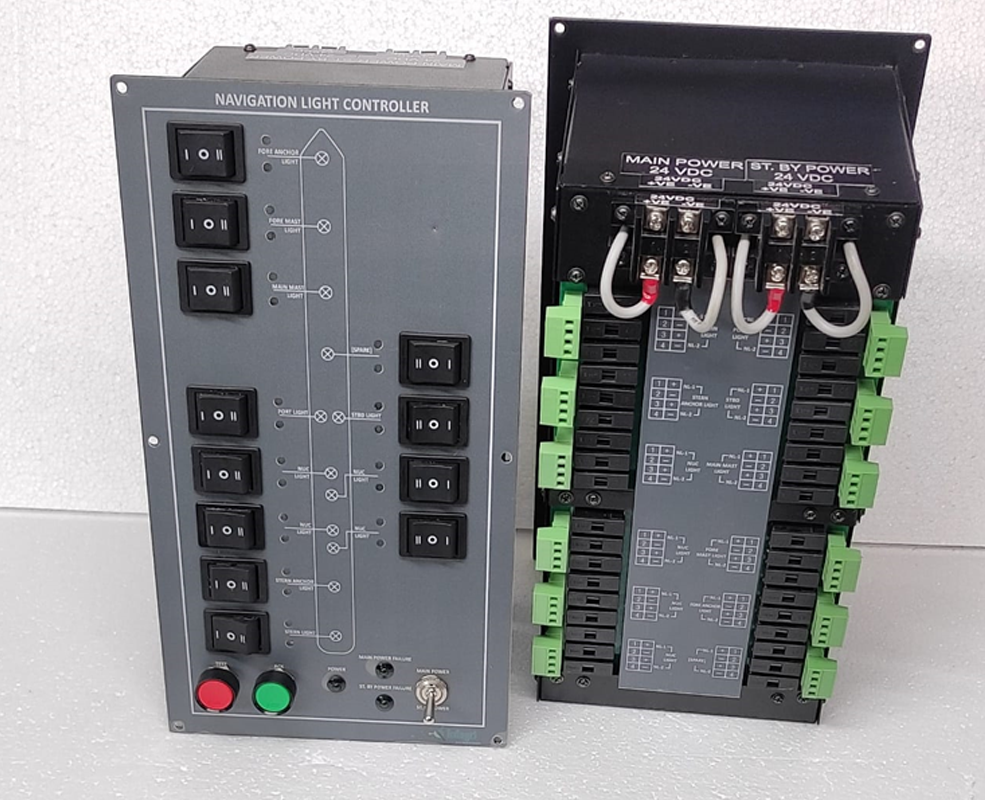
FRONT OPERATOR PANEL • REAR TERMINAL / CONTROL ASSEMBLY
| Main Power Supply | 24 V DC |
| Standby Power Supply | 24 V DC |
The Dynatek Navigation Light Controller provides a centralized operator interface for designated vessel navigation and signal-light circuits. A clearly laid-out mimic diagram, individual rocker switches and visual indicators help operators identify and control assigned circuits. The photographed unit is arranged for 24 V DC main and 24 V DC standby supplies, with a separate rear assembly for electrical connections.
A configurable control panel for shipbuilders, marine electrical contractors and vessel refit projects.
| Individual circuit control | Dedicated rocker switches for assigned navigation and signal-light circuits. |
| Visual status indication | Indicators are arranged alongside the front-panel mimic diagram. |
| Lamp-failure monitoring | Whenever a navigation lamp fails or its bulb fuses, the corresponding RED LED indicator starts flashing, accompanied by an audible beep alarm to alert the operator. When the ACK (Acknowledge) button is pressed, the audible alarm is silenced, while the RED LED glows steadily to indicate the fault condition. Once the navigation lamp is restored to normal operation, the corresponding GREEN LED indicator glows and RED Led off, confirming that the lamp is functioning correctly. |
| Automatic standby changeover | The Navigation Light Controller normally operates on the 24 V DC main power supply. In the event of a main power supply failure, an audible beep alarm alerts the operator, who can manually switch the system to the 24 V DC standby power supply. Similarly, when the standby power supply fails, the operator can manually switch back to the main power supply once it is available. |
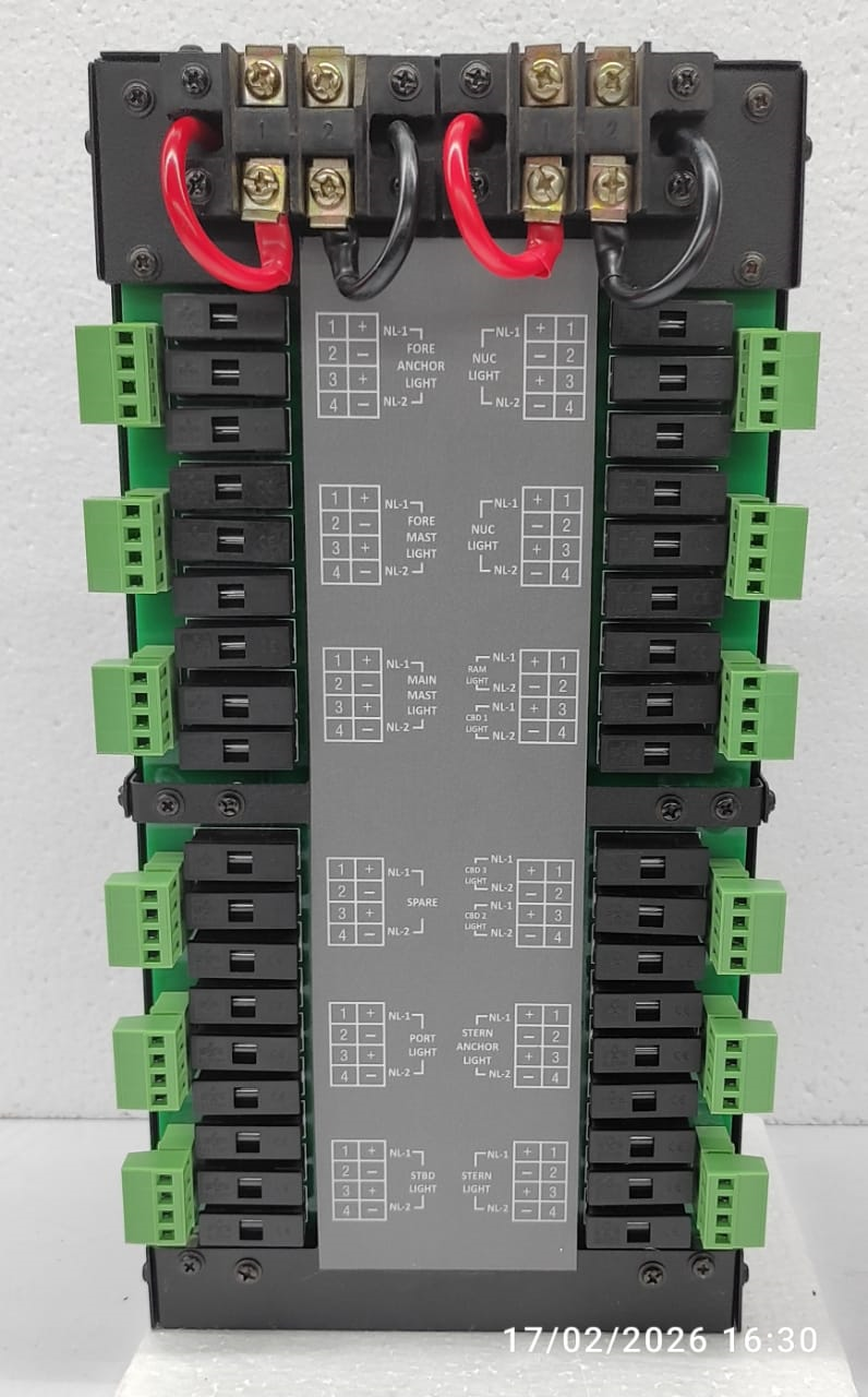
| Rear connection assembly | The rear panel is equipped with sturdy, detachable, heavy-duty connectors, with a dedicated 2-pin connector for each navigation lamp. Individual fuses are provided for each lamp circuit to ensure effective circuit protection. In the event of a short circuit, the corresponding fuse blows, interrupting the affected circuit and helping protect the system from further electrical damage. |
| “TEST” Push button | When the “TEST” push button is pressed, all RED and GREEN LED indicators illuminate, and the audible beep alarm is activated to verify the proper functioning of the visual and audible alarm indicators. |
| “ACK” Push button | To acknowledge the fault (Fused Navigation Lamp) |
| Product | - | Navigation Light Controller |
| Main / standby supply | - | 24 V DC / 24 V DC |
| Operator interface | - | Rocker switches, push buttons, visual indicators and mimic diagram |
| Monitoring functions | - | Lamp-failure monitoring and automatic standby changeover, as specified for this configuration |
| Mounting | - | Flush Mounting |
| Marine approvals | - | Compliance with Marine Application |
| Mechanical dimensions | - | Front Plate : 335 x 180mm Cut-Out : 308 x 154 mm Depth : 165 mm |
Application-specific marine control panels | OEM enquiries welcome
